
Page 15 - Vcenter-AX350AX800 (5 axes)
P. 15
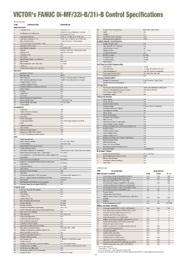
VICTOR's FANUC 0i-MF/32i-B/31i-B Control Specifications


          Standard
          ITEM    SPECIFICATION        DESCRIPTION
          Controlled Axes
          1.  Controlled Axes          3 Axes (X, Y, Z)       30.  Program Stop / Program End  M00 / M01 / M02 / M30
                                       Position / Linear interpolation / Circular   31.  Reset  Std.
          2.  Simultaneous Controlled Axes
                                       interpolation (3 / 3 / 2)  32.  Scaling              G51
          3.  Least Input Increment    0.001 mm / 0.0001 inch / 0.001 deg.  33.  Coordinate System Rotation  G68
          4.  Least Input Increment 1 / 10  0.0001 mm / 0.00001 inch / 0.0001 deg.  34.  Tilted work plane command  G68.2
          5.  Max, command value       Ô99999.999mm (Ô9999.9999in)  Auxiliary Spindle Speed Function
          6.  Fine Acceleration & Deceleration Control  Std.  1.  Auxiliary Function Lock   Std.
          7.  High Speed HRV Control   Std.                   2.  High Speed M / S / T Interface  Std.
          8.  Inch / Metric Conversion  Std. (G20 / G21)      3.  Spindle Speed Function    Std.
          9.  Interlock                All Axes / Each Axis / Cutting Block Start  4.  Spindle Override  50 ~ 120%
          10.  Machine Lock            All Axes / Each Axis   5.  1 st  Spindle Orientation  Std.
          11.  Emergency Stop          Std.                   6.  M Code Function           M3 digit
          12.  Over-travel             Std.                   7.  S Code Function           S5 digit
          13.  Stored Stroke Check 1 and Check 2  Std.        8.  T Code Function           T2 digit
          14.  Mirror Image            Each Axis              9.  Rigid tapping             Std.
          15.  Mirror Image M73, M74, M75, M76  X, Y Axes
          16.  Follow-up               Std.                   Tool Function & Tool Compensation  T8 digit
                                                                  Tool Function
                                                              1.
          17.  Position switch (with Victo's own PLC)   Std.
                                                              2.  Tool Offset Pairs         Ô6-digit, 400 (0i/32i), 999 (31i)
          Operation                                           3.  Tool Offset Memory C      Std. (D/H codes are separated)
          1.  Automatic Operation      Std.                   4.  Tool Length Compensation  G43-G44, G45-G48, G49
          2.  MDI Operation            MDI B                  5.  Cutting Compensation C    Std.
          3.  DNC Operation            Reader / Puncher Interface is Required  Accuracy Compensation
          4.  DNC Operation with Memory Card  PCMCIA Card Attachment is Required  1.  Backlash Compensation  Rapid Traverse / Cutting Feed
          5.  Program Number Search    Std.                   2.  Stored Pitch Error Compensation  Std.
          6.  Sequence Number Search   Std.                   Edit Operation
          7.  Sequence Number comparison and stop  Std.       1.  Part Program Storage Length (in total)  1280m (512KB) (0i/32i), 2560m (31i)
          8.  Buffer Register          Std.                   2.  Number of Registerable programs (in total)  400 (0i/32i),1000 (31i)
          9.  Dry Run                  Std.                   3.  Part Program Editing / Protect  Std.
          10.  Single Block            Std.                   4.  Background Editing        Std.
          11.  JOG Feed                Std.
          12.  Manual Reference Position Return  Std.         Setting and Display
          13.  Manual Handle Feed      1 Unit / Each Path     1.  Status Display            Std.
          14.  Manual Handle Feed Rate  X1, X10, X100         2.  Clock Function            Std.
          15.  Z Axis Neglect          Std.                   3.  Current Position Display  Std.
                                                              4.  Program Display           Program name 31 characters
          Interpolation                                       5.  Parameter Setting and Display  Std.
          1.  Positioning              G00                    6.  Self Diagnosis Function   Std.
          2.  Single Direction Positioning  G60               7.  Alarm Display             Std.
          3.  Exact Stop Mode          G61                    8.  Alarm History Display     25
          4.  Exact Stop               G09                    9.  Operation History Display  Std.
          5.   Linear Interpolation    G01                    10.  Help Function            Std.
          6.   Circular Interpolation  G02, G03 (multi-quadrant is possible).  11.  Run Hour and Parts Count Display  Std.
          7.  Dwell                    G04
          8.  Helical interpolation    Std.                   12.  Actual Cutting Feedrate Display  Std.
                                                              13.
                                                                                            Std.
                                                                  Display of Spindle Speed and T Code At All Screens
          9.  Skip Function            G31                    14.  Graphic Function         Std.
          10.  Reference Position Return  G28                 15.  Dynamic graphic display  Std.
          11.  Reference Position Return Check  G27           16.  Servo Setting Screen     Std.
          12.  2 nd  / 3 rd  / 4 th  Reference Position Return  Std.
                                                              17.  Spindle Setting Screen   Std.
          Feed                                                18.  Display of Hardware and Software Configuration  Std.
          1.  Rapid Traverse Rate      Std.                   19.  Multi-Language Display   Std.
          2.  Rapid Traverse Override   F0, 25%, 50%, 100%    20.  Data Protection Key      Std.
          3.  Feed Per Minute          G94 (mm / min)         21.  Erase CRT Screen Display  Std.
          4.  Tangential Speed Constant Control  Std.         22.  Machining Condition Selecting Screen  Std.
          5.  Cutting Feed rate Clamp  Std.                   23.  Color LCD / MDI          10.4"(0i/32i/31i)
          6.  Automatic Acceleration / Deceleration  Rapid traverse: linear; Cutting feed: exponential  Data Input / Output
          7.  Rapid traverse Bell–shaped Acc. / Deceleration   Std. (G00)  1.  Reader / Puncher Interface  RS-232 interface
              Bell–shaped Acc. / Deceleration Before & After Cutting Feed
          8.                           Std. (G01)             2.  External Work piece number search  9999
              Interpolation                                   3.  Memory Card Interface     Std.
          9.  Automatic Corner Deceleration  Std. (G64)       4.  Embedded Ethernet (10Mbps)  Std.
              Linear Acc / Deceleration Before & After Cutting Feed
          10.                          Std. (G01)             5.  USB device                Std.
              Interpolation
          11.  Feed rate Override      0 ~ 150%
          12.  Jog Override            0 ~ 100%               OPTIONS
          13.  Automatic Corner Override  G62.                ITEM      SPECIFICATION             DESCRIPTION
          14.  Feed Stop               Std.                   With hardware included
          15.  AI contour control (AICC, G05.1) (in total)  200 blocks (0i/32i with AICC-2)  1.  Conversational programming (Manual Guide i)  0i-M  32i-B  31i-B
                                                                                                           Std.
                                                                                              Std.
                                                                                                     Std.
          16.  AICC-2 + High speed processing (G05.1) (in total)  600 blocks (31i)  2  Conversational programming (Super Cap i)  N.A.  N.A.  N.A.
          17.  Jerk Control            Std. (31i)             3.  Data server (with PCB and CF card 1GB)   Std.
          18.  Rigid Tapping Bell–Shaped Acc./Deceleration  Std.  4.  Fast Ethernet (100Mbps, available in Data server)  Std.  Std.
          19.  Feed rate clamp by arc radius (G02/G03)  Std.
                                                              5.  Tool life management (2 buttons on control panel)
          Program Input                                       6.  Part Program Storage Length 5120m (2MB in total)
          1.   EIA / ISO Automatic Recognition  Std.          7.  Part Program Storage Length 8MB in total  N.A.  N.A.
          2.  Label Skip               Std.                   8.  Program restart
          3.  Parity Check             Std.                   9.  Optional block skip 9 blocks
          4.  Control In / Out         Std.                       High Precision Contour Control (HPnanoCC, with RISC
          5.  Optional Block Skip      1                      10.  board)* 1                  N.A.  N.A.   Std.
          6   Max. Programmable Dimension  Ô8-Digit           11.  Profibus
          7.  Program Number           O4-Digit               12.  5-axis simultaneous control  N.A.  N.A.   (31i-B5)
          8.  Sequence Number          N5-Digit               Without hardware included
          9.  Absolute / Incremental Programming  G90 / G91   13.  AI contour control II (AICC-2, G05.1, 200 blocks) * 2  Std.  Std.  Std.
          10.   (Pocket Calculator Type) Decimal Point Programming  Std.  14.  Look ahead block expansion (1000 blocks in total) * 2  N.A.  N.A.
          11.  Input Unit 10 Time Multiply  Std.              15.  Tool load monitoring (with Victor own PLC)
          12.  Plane Selection         G17, G18, G19          16.  Programmable mirror image (G50.1)
          13.  Rotary Axis Designation  Std.                  17.  Bi-directional Pitch Error Compensation
          14.  Rotary Axis Roll-Over Function  Std.           18.  Addition of tool pairs for tool life management 512 sets  N.A.
          15.  Polar coordinate Command  G16                  19.  Cylindrical interpolation (G7.1) (used on 4th-axis)  Std.
          16.  Coordinate System Setting  Std.                20.  Interruption type custom macro  N.A.
          17.  Automatic Coordinate System Setting  Std.      21.  Addition of work-piece coordinate systems 300 sets  N.A.  N.A.
          18.  Work piece Coordinate System  G52, G53, G54 ~ G59  22.  Exponential interpolation (G2.3)  N.A.  N.A.
          19.  Addition of Workpiece Coordinate System Pair  48 Pairs  23.  Smooth interpolation  N.A.  N.A.
          20.  Manual Absolute On And Off  Std.               24.  Spiral/conical interpolation  N.A.  N.A.
          21.  Optional Chamfering / Corner R  Std.           25.  Polar coordinate interpolation  N.A.
          22.  Programmable Data Input  G10                   26.  Floating reference position return  N.A.  N.A.
          23.  Sub Program Call        4 (0i/32i) or 10 (31i) folds nested  27.  Hypothetical axis interpolation (G07)  N.A.  N.A.
          24.  Custom macro B          Std.                   28.  Tool retract and return (G10.6 with Victor own PLC)  N.A.  N.A.
          25.  Addition of Custom Macro Common Variables  #100~#199,#500~#999  29.  NURBS interpolation (only avail. in HPCC/RISC)  N.A.  N.A.
          26.  Canned Cycles For Milling  G73 / G74 / G76, G80-G89, G98 / G99  *1. Block addressing time:
          27.  Small hole peck drilling cycle  G83               -  2 ms for AICC-2 (0i-F/31i-B)
          28.  Circular Interpolation by R Programming  Std.      - 1ms for HPCC (max. cutting feed 60 m/min) (31i-B)
          29.  Program Format          FANUC std. format         - 0.4ms for AI HPCC and AI nano HPCC (150m/min) (31i-B) and AICC-2+ High speed processing (31i-B)
                                                             14